Difference between revisions of "Week 2 Lab"
From Robert-Depot
(→Set up Breadboard) |
(→Set up Breadboard) |
||
| Line 6: | Line 6: | ||
[[Image:Power_hookup.png]] | [[Image:Power_hookup.png]] | ||
## verify that this worked (with multimeter, or LED test). | ## verify that this worked (with multimeter, or LED test). | ||
| − | [[Image:Verify_power.jpg] | + | [[Image:Verify_power.jpg]] |
| − | |||
=== Simple Digital Out === | === Simple Digital Out === | ||
Revision as of 07:04, 7 April 2009
Set up Breadboard
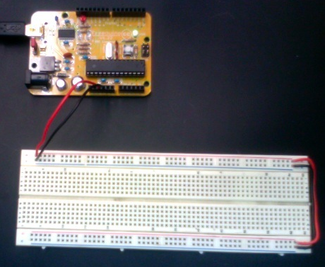
- Power from arduino to breadboard:
- connect positive and negative power buses on proto board
- run power, "5V" and "GND" from arduino to breadboard.
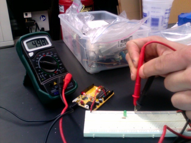
- verify that this worked (with multimeter, or LED test).
Simple Digital Out
- Set up LED on external board, check that it works
- change Blink program (from Sketchbook->Examples->Digital) to run off of one of the external digital pins
- Pins 0-13 on the "Digital" side of your board. By the power light.
- connect the LED to that pin.
- Does it work?

