Difference between revisions of "Students/ScottJones"
(uwe) |
(→Final Project Documentation) |
||
| (11 intermediate revisions by the same user not shown) | |||
| Line 1: | Line 1: | ||
I am a senior transfer student in the visual arts media major. My main focus is film and video, but I also love working with my hands, building and tinkering. I am a musician, so I would love to be able to use knowledge from this class to use in fixing/building equipment. I frequent swap meets, thrift stores and garage sales, so I am always collecting and looking for interesting 'junk' that could somehow come to use or simply be displayed on my mantle. I also ride and work on mopeds, scooters and small displacement motorcycles. Some of my interests have involved simple electronics work and soldering, but I still don't feel like a have the basic knowledge to understand how everything works. I am looking forward to this class! | I am a senior transfer student in the visual arts media major. My main focus is film and video, but I also love working with my hands, building and tinkering. I am a musician, so I would love to be able to use knowledge from this class to use in fixing/building equipment. I frequent swap meets, thrift stores and garage sales, so I am always collecting and looking for interesting 'junk' that could somehow come to use or simply be displayed on my mantle. I also ride and work on mopeds, scooters and small displacement motorcycles. Some of my interests have involved simple electronics work and soldering, but I still don't feel like a have the basic knowledge to understand how everything works. I am looking forward to this class! | ||
| + | |||
| + | ---- | ||
| + | http://farm4.static.flickr.com/3550/3683082953_cc250b32c8.jpg | ||
| + | |||
| + | http://farm4.static.flickr.com/3563/3305324997_f25655149c.jpg | ||
| + | |||
| + | http://farm1.static.flickr.com/108/365658644_c8f72a6503.jpg | ||
| + | |||
| + | http://farm1.static.flickr.com/104/365658672_4ea5dc81bf.jpg | ||
| + | |||
| + | |||
| + | == Midterm == | ||
| + | |||
| + | My project consists of a simple circuit with one button that turns on two laser pointers. The pointers are wire in parallel as to retain their full brightness. The witch is a push-on, push-off switch. The lasers are housed in each of the eye sockets of a teddy bear bank and the switch is mounted to look like the bear is holding it in its arm. Push the button and the eyes of the bear light up and shoot out laser beams. | ||
| + | |||
| + | Humor and irony are motifs I like to explore in my art work, so this was the motivation behind this project. I wanted to take something that was ridiculously cute and change it in a way that would make it ridiculously terrifying. That being said, I wanted to retain the original look of the bear to keep the irony going and make it more inconspicuous. Once the button is pushed, the bear is transformed into something completely different. | ||
| + | |||
| + | The construction of the circuit was pretty straight forward. The battery contacts on each of the lasers is hard wired now. The positive leads are connected through the switch, then to my 5V power source coming from my breadboard. The trickiest part of the construction was mounting the components inside the bear. It's made of a hard composite plastic, so I had to cut out the bottom to gain access to the inside. I also had to drill out the eye sockets to accept the lasers, and drill a hole for the switch. | ||
| + | |||
| + | Given more time a resources I would like to create some sort of bracket system inside the head that keeps the lasers pointing in the same direction and orientation. I would also like to find a transparent lens which more closely resembles the original eyes of the bear, so that the laser beams would shine through. Permanently wiring the circuit (so I don't have to use the breadboard) is another thing I would do to complete this project in the future. | ||
| + | |||
| + | http://farm5.static.flickr.com/4040/4331063248_51447a52ff_o.jpg | ||
| + | |||
| + | http://farm5.static.flickr.com/4051/4331039162_f89391a090.jpg | ||
| + | |||
| + | http://farm5.static.flickr.com/4016/4330304063_d9141ee71c.jpg | ||
| + | |||
| + | http://farm3.static.flickr.com/2713/4330304167_9635b8582d.jpg | ||
| + | |||
| + | |||
| + | == Final == | ||
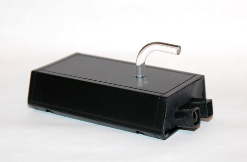
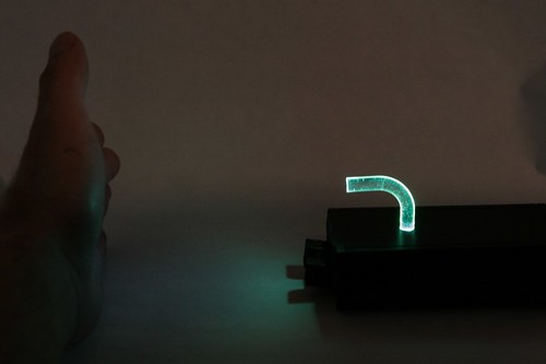
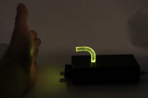
| + | For my final project I am proposing a proximity controlled light display. This will involve an infrared proximity sensor connected through the arduino to a high powered RGB LED light. The distance to the sensor will control the color of the light being displayed. Since I am using a high power LED, I plan on projecting the light against a wall so the entire wall is illuminated. I will most likely set up the sensor so that when you walk closer or farther away, the color of the light will change. | ||
| + | |||
| + | The thought behind this piece is the idea of proximity and personal space. Depending on the color at certain proximities, the color will either be inviting or not, prompting the viewer to proceed closer or further away. I need to put some more thought into how I will display the piece once it is built and try to figure out a way I can use this technology to create more of a discussion. | ||
| + | |||
| + | |||
| + | == Final Project Documentation == | ||
| + | |||
| + | '''"External, visible results increase proportionately to your distance from the perfect state" - Wols, Aphorisms (1944)''' | ||
| + | |||
| + | http://farm5.static.flickr.com/4047/4444084682_364d899b4e.jpg | ||
| + | |||
| + | http://farm5.static.flickr.com/4018/4443313003_778cd0da69.jpg | ||
| + | |||
| + | http://farm3.static.flickr.com/2793/4444084328_3b9c45a40e.jpg | ||
| + | |||
| + | http://farm5.static.flickr.com/4022/4443312703_f1014774d7.jpg | ||
| + | |||
| + | http://farm5.static.flickr.com/4036/4444084136_5da2a09069.jpg | ||
| + | |||
| + | http://farm3.static.flickr.com/2781/4443312611_684383a38c.jpg | ||
| + | |||
| + | Video: http://www.flickr.com/photos/scottwj/4443367599/ | ||
| + | |||
| + | '''Construction:''' | ||
| + | |||
| + | http://farm3.static.flickr.com/2803/4444112586_49a13b8764.jpg | ||
| + | |||
| + | ---- | ||
| + | Source Code: | ||
| + | |||
| + | int potpin = 2; // Switch connected to digital pin 2 | ||
| + | |||
| + | int rpin = 8; | ||
| + | int gpin = 9; | ||
| + | int bpin = 10; | ||
| + | float h; | ||
| + | int h_int; | ||
| + | int r=0, g=0, b=0; | ||
| + | |||
| + | int val=0; | ||
| + | |||
| + | void h2rgb(float h, int &R, int &G, int &B); | ||
| + | |||
| + | void setup() // run once, when the sketch starts | ||
| + | { | ||
| + | Serial.begin(9600); // set up Serial library at 9600 bps | ||
| + | } | ||
| + | |||
| + | |||
| + | void loop() // run over and over again | ||
| + | { | ||
| + | val=analogRead(potpin); // Read the pin and display the value | ||
| + | //Serial.println(val); | ||
| + | h = ((float)val)/532; | ||
| + | h_int = (int) 360*h; | ||
| + | h2rgb(h,r,g,b); | ||
| + | Serial.print("Potentiometer value: "); | ||
| + | Serial.print(val); | ||
| + | Serial.print(" = Hue of "); | ||
| + | Serial.print(h_int); | ||
| + | Serial.print("degrees. In RGB this is: "); | ||
| + | Serial.print(r); | ||
| + | Serial.print(" "); | ||
| + | Serial.print(g); | ||
| + | Serial.print(" "); | ||
| + | Serial.println(b); | ||
| + | |||
| + | analogWrite(rpin, r); | ||
| + | analogWrite(gpin, g); | ||
| + | analogWrite(bpin, b); | ||
| + | } | ||
| + | |||
| + | void h2rgb(float H, int& R, int& G, int& B) { | ||
| + | |||
| + | int var_i; | ||
| + | float S=1, V=1, var_1, var_2, var_3, var_h, var_r, var_g, var_b; | ||
| + | |||
| + | if ( S == 0 ) //HSV values = 0 ÷ 1 | ||
| + | { | ||
| + | R = V * 255; | ||
| + | G = V * 255; | ||
| + | B = V * 255; | ||
| + | } | ||
| + | else | ||
| + | { | ||
| + | var_h = H * 6; | ||
| + | if ( var_h == 6 ) var_h = 0; //H must be < 1 | ||
| + | var_i = int( var_h ) ; //Or ... var_i = floor( var_h ) | ||
| + | var_1 = V * ( 1 - S ); | ||
| + | var_2 = V * ( 1 - S * ( var_h - var_i ) ); | ||
| + | var_3 = V * ( 1 - S * ( 1 - ( var_h - var_i ) ) ); | ||
| + | |||
| + | if ( var_i == 0 ) { | ||
| + | var_r = V ; | ||
| + | var_g = var_3 ; | ||
| + | var_b = var_1 ; | ||
| + | } | ||
| + | else if ( var_i == 1 ) { | ||
| + | var_r = var_2 ; | ||
| + | var_g = V ; | ||
| + | var_b = var_1 ; | ||
| + | } | ||
| + | else if ( var_i == 2 ) { | ||
| + | var_r = var_1 ; | ||
| + | var_g = V ; | ||
| + | var_b = var_3 ; | ||
| + | } | ||
| + | else if ( var_i == 3 ) { | ||
| + | var_r = var_1 ; | ||
| + | var_g = var_2 ; | ||
| + | var_b = V ; | ||
| + | } | ||
| + | else if ( var_i == 4 ) { | ||
| + | var_r = var_3 ; | ||
| + | var_g = var_1 ; | ||
| + | var_b = V ; | ||
| + | } | ||
| + | else { | ||
| + | var_r = V ; | ||
| + | var_g = var_1 ; | ||
| + | var_b = var_2 ; | ||
| + | } | ||
| + | |||
| + | R = (1-var_r) * 255; //RGB results = 0 ÷ 255 | ||
| + | G = (1-var_g) * 255; | ||
| + | B = (1-var_b) * 255; | ||
| + | } | ||
| + | } | ||
Latest revision as of 14:04, 18 March 2010
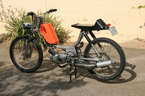
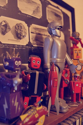
I am a senior transfer student in the visual arts media major. My main focus is film and video, but I also love working with my hands, building and tinkering. I am a musician, so I would love to be able to use knowledge from this class to use in fixing/building equipment. I frequent swap meets, thrift stores and garage sales, so I am always collecting and looking for interesting 'junk' that could somehow come to use or simply be displayed on my mantle. I also ride and work on mopeds, scooters and small displacement motorcycles. Some of my interests have involved simple electronics work and soldering, but I still don't feel like a have the basic knowledge to understand how everything works. I am looking forward to this class!


Midterm
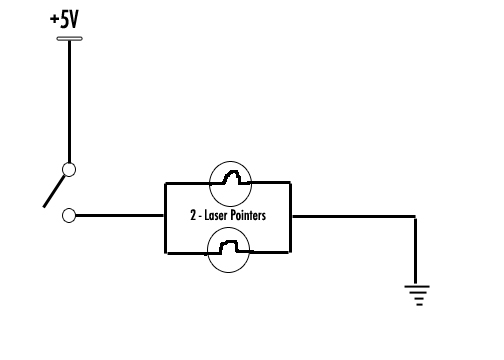
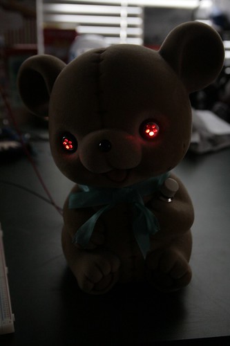
My project consists of a simple circuit with one button that turns on two laser pointers. The pointers are wire in parallel as to retain their full brightness. The witch is a push-on, push-off switch. The lasers are housed in each of the eye sockets of a teddy bear bank and the switch is mounted to look like the bear is holding it in its arm. Push the button and the eyes of the bear light up and shoot out laser beams.
Humor and irony are motifs I like to explore in my art work, so this was the motivation behind this project. I wanted to take something that was ridiculously cute and change it in a way that would make it ridiculously terrifying. That being said, I wanted to retain the original look of the bear to keep the irony going and make it more inconspicuous. Once the button is pushed, the bear is transformed into something completely different.
The construction of the circuit was pretty straight forward. The battery contacts on each of the lasers is hard wired now. The positive leads are connected through the switch, then to my 5V power source coming from my breadboard. The trickiest part of the construction was mounting the components inside the bear. It's made of a hard composite plastic, so I had to cut out the bottom to gain access to the inside. I also had to drill out the eye sockets to accept the lasers, and drill a hole for the switch.
Given more time a resources I would like to create some sort of bracket system inside the head that keeps the lasers pointing in the same direction and orientation. I would also like to find a transparent lens which more closely resembles the original eyes of the bear, so that the laser beams would shine through. Permanently wiring the circuit (so I don't have to use the breadboard) is another thing I would do to complete this project in the future.


Final
For my final project I am proposing a proximity controlled light display. This will involve an infrared proximity sensor connected through the arduino to a high powered RGB LED light. The distance to the sensor will control the color of the light being displayed. Since I am using a high power LED, I plan on projecting the light against a wall so the entire wall is illuminated. I will most likely set up the sensor so that when you walk closer or farther away, the color of the light will change.
The thought behind this piece is the idea of proximity and personal space. Depending on the color at certain proximities, the color will either be inviting or not, prompting the viewer to proceed closer or further away. I need to put some more thought into how I will display the piece once it is built and try to figure out a way I can use this technology to create more of a discussion.
Final Project Documentation
"External, visible results increase proportionately to your distance from the perfect state" - Wols, Aphorisms (1944)



Video: http://www.flickr.com/photos/scottwj/4443367599/
Construction:

Source Code:
int potpin = 2; // Switch connected to digital pin 2
int rpin = 8; int gpin = 9; int bpin = 10; float h; int h_int; int r=0, g=0, b=0;
int val=0;
void h2rgb(float h, int &R, int &G, int &B);
void setup() // run once, when the sketch starts {
Serial.begin(9600); // set up Serial library at 9600 bps
}
void loop() // run over and over again
{
 val=analogRead(potpin);    // Read the pin and display the value
 //Serial.println(val);
 h = ((float)val)/532;
 h_int = (int) 360*h;
 h2rgb(h,r,g,b);
 Serial.print("Potentiometer value: ");
 Serial.print(val);
 Serial.print(" = Hue of ");
 Serial.print(h_int);
 Serial.print("degrees. In RGB this is: ");
 Serial.print(r);
 Serial.print(" ");
 Serial.print(g);
 Serial.print(" ");
 Serial.println(b);
 analogWrite(rpin, r);
 analogWrite(gpin, g);
 analogWrite(bpin, b);
}
void h2rgb(float H, int& R, int& G, int& B) {
 int var_i;
 float S=1, V=1, var_1, var_2, var_3, var_h, var_r, var_g, var_b;
 if ( S == 0 )                       //HSV values = 0 ÷ 1
 {
   R = V * 255;
   G = V * 255;
   B = V * 255;
 }
 else
 {
   var_h = H * 6;
   if ( var_h == 6 ) var_h = 0;      //H must be < 1
   var_i = int( var_h ) ;            //Or ... var_i = floor( var_h )
   var_1 = V * ( 1 - S );
   var_2 = V * ( 1 - S * ( var_h - var_i ) );
   var_3 = V * ( 1 - S * ( 1 - ( var_h - var_i ) ) );
   if      ( var_i == 0 ) {
     var_r = V     ;
     var_g = var_3 ;
     var_b = var_1 ;
   }
   else if ( var_i == 1 ) {
     var_r = var_2 ;
     var_g = V     ;
     var_b = var_1 ;
   }
   else if ( var_i == 2 ) {
     var_r = var_1 ;
     var_g = V     ;
     var_b = var_3 ;
   }
   else if ( var_i == 3 ) {
     var_r = var_1 ;
     var_g = var_2 ;
     var_b = V     ;
   }
   else if ( var_i == 4 ) {
     var_r = var_3 ;
     var_g = var_1 ;
     var_b = V     ;
   }
   else                   {
     var_r = V     ;
     var_g = var_1 ;
     var_b = var_2 ;
   }
   R = (1-var_r) * 255;                  //RGB results = 0 ÷ 255
   G = (1-var_g) * 255;
   B = (1-var_b) * 255;
 }
}