Difference between revisions of "Week 3 Lab"
From Robert-Depot
(→Analog Input) |
(→Analog Input) |
||
| Line 3: | Line 3: | ||
== Analog Input == | == Analog Input == | ||
* File->Sketchbook->Analog->AnalogInput | * File->Sketchbook->Analog->AnalogInput | ||
| − | + | === Potentiometer === | |
[[Image:Pot_in.png]] | [[Image:Pot_in.png]] | ||
* Q: What will the voltage at A_IN be? What are the upper and lower values? | * Q: What will the voltage at A_IN be? What are the upper and lower values? | ||
Revision as of 22:10, 12 April 2009
from Electronic Technologies for Art
Contents
Analog Input
- File->Sketchbook->Analog->AnalogInput
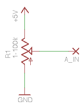
Potentiometer
- Q: What will the voltage at A_IN be? What are the upper and lower values?
- The important part of this sketch is the line where the microprocessor reads the analog input:
val = analogRead(potPin); // read the value from the sensor
- Q: Looking at the Arduino help for that function (
analogRead()), what do you think the valuevalwill be for those highest and lowest voltages at V_IN? - Q: How can you verify your guess? (... I have two ideas ... )
other loads
- photoresistor from your 147A kit... 160k - ~10k (depending on your lighting conditions).
- Q: With the same 10k resistor from the schematic above, what range of voltages (and corresponding data values) would you expect to see with this?
- strain gauge
- ultrasonic rangefinder:
Analog Output
LED Dimming
- File->Sketchbook->Examples->Analog->Fading
analogWrite(ledpin, value); // sets the value (range from 0 to 255)
PWM (pulse width modulation)
- lights, fading
<youtube v="62gWVWCyw_w" loop="true"/>
Motor Speed Control
- Basic motor control (DC motors) see week 5
Sound, Tone Generation
- sounds, tone generation
