Difference between revisions of "Week 4 Lab"
(→controlling from a Processing app) |
(→controlling from a Processing app) |
||
| Line 52: | Line 52: | ||
* In Processing, open a new sketch, and copy this code into it. Save this sketch as "arduino_test" or something like that. It should look like this: | * In Processing, open a new sketch, and copy this code into it. Save this sketch as "arduino_test" or something like that. It should look like this: | ||
[[Image:Arduino_serialtest_processing.png]] | [[Image:Arduino_serialtest_processing.png]] | ||
| − | ** Try running this sketch. When you do, it may give you an error about "COM1" or something of that sort. You need to tell the program what serial port your arduino is connected to. | + | ** Try running this sketch. When you do, it may give you an error about "COM1" or something of that sort. You need to tell the program what serial port your arduino is connected to. When the program runs, you will see a list of Serial ports, you can see mine in the picture above. On my comnputer, I see that my serial port is the "tty.usbserial-A900acnt", which is listed as device number 2 ([2]), so I go back into the processing code and change the line that says <code>port = new Serial</code>... to read <code>port = new Serial(this, Serial.list()[2], 9600);</code> |
| − | |||
| − | |||
| − | |||
| − | |||
| − | |||
| − | |||
| − | |||
| − | |||
| − | |||
| − | |||
| − | |||
| − | |||
| − | |||
| − | |||
| − | |||
** Now if I run the sketch again, I know that it will be properly communicating with the Arduino. You will need to modify that line to reflect whichever serial port your arduino is connected to. | ** Now if I run the sketch again, I know that it will be properly communicating with the Arduino. You will need to modify that line to reflect whichever serial port your arduino is connected to. | ||
* Upload the original (unmodified) Dimmer code to your arduino in the arduino software. Your processor should now be running that code... waiting for input! | * Upload the original (unmodified) Dimmer code to your arduino in the arduino software. Your processor should now be running that code... waiting for input! | ||
Revision as of 20:48, 20 April 2009
Contents
Interfacing
- Download and install processing http://processing.org/download
Basic Serial Interface
- Open the Sketchbook->Examples->Communication->ASCIITable, and run it on your processor.
- There are two different
Basic text output from the microcontroller is accomplished with
Serial.print()
and
Serial.println()
- You can use this to verify values and behavior inside of a program, for debugging, for example:
- Displaying values of sensors
Serial.print(val) - Checking program flow.
- Displaying values of sensors
- Assuming you have a sensor which produces an analog output, hook it up to one of the Analog Inputs on your arduino. If you do not have a sensor, use the light sensor from last week. If you are not sure how your sensor works, come over and talk to me and we can try to figure it out.
- Run a short program to read data from that sensor and send it to the Serial port.
- Click on the Serial Monitor in the Arduino software, and see what the output from your Sensor is. How does it change as you manipulate your sensor?
Dimmer
Controlling a physical LED with the computer.
- Compile the Examples->Communication->Dimmer example, and upload it to your board. This example sets up communication on the serial port (in the
void setup()function, and then reads values from theSerialinput, and writes them to theledPinoutput. - Connect up the TIP120 driver circuit and motor from last week to the
ledPin(pin 9). You should now be able to control the motor speed via the serial port on your computer... interesting... - Click on the "Serial Monitor" button (to the right of the "Upload to Board" button) in the arduino software. Try sending different values to the board. Type in numbers and press Enter (or click on the "Send" button, either will work).
- What behavior do you observe?
- Can you get the motor to speed up or slow down?
modifying for rudimentary keyboard control
As-is, the Dimmer code is not very useful for controlling through the serial terminal like this. Now we are going to modify it to so that it works a little better. Our goal is to be able to set the speed of the motor typing the numbers 0-9 on the keyboard. 9 will go fastest (nearly full speed), and 0 will be a dead stop.
- Make a new copy of the Dimmer example, and replace the original
loop()code with this new one:
void loop()
{
 char val;
 byte out_speed;
 // check if data has been sent from the computer
 if (Serial.available()) {
   // read the most recent byte (which will be from 0 to 255)
   val = Serial.read();

   if((val>='0')&&(val<='9')) {
     val=val-'0'; // set value between 0 and 9.
     out_speed=val*28; // set out_speed between 0 and 252.
     analogWrite(ledPin, out_speed);
   }
 }
}
- What I have done is change the
Serial.read()andanalogWrite()from before. Now we are reading acharrather than abytefrom the Serial port, and we are checking whether this character it reads is one of the characters between '0' and '9': a letter on the keyboard was pressed, it is one of the numbers? If it is (if((val>='0')&&(val<='9'))) then we will set the speed of the motor proportionally. - Compile and upload this sketch to the board, and try it out. Start the Serial Monitor again, and try sending the numbers 0-9 on the keyboard, the motor should speed up and slow down appropriately.
- EXPLANATION: What did we just do? The problem in our original Dimmer code was that the microcontroller was looking just at the binary value of the data it was receiving, but did not know what key was pressed. So, when we typed the number 0, which happens to have a binary value of ___ in the ASCII table, it will set the speed to that value, not to 0. We changed the program so the microcontroller is looking for the specific characters, '0' to '9', and then doing the appropriate math to set the output to the right speed.
controlling from a Processing app
Save your modified Dimmer example, and revert back to the original dimmer code. We are now going to learn how to control the processor from the processing App. See the commented Processing code hidden at the end of the Dimmer program.
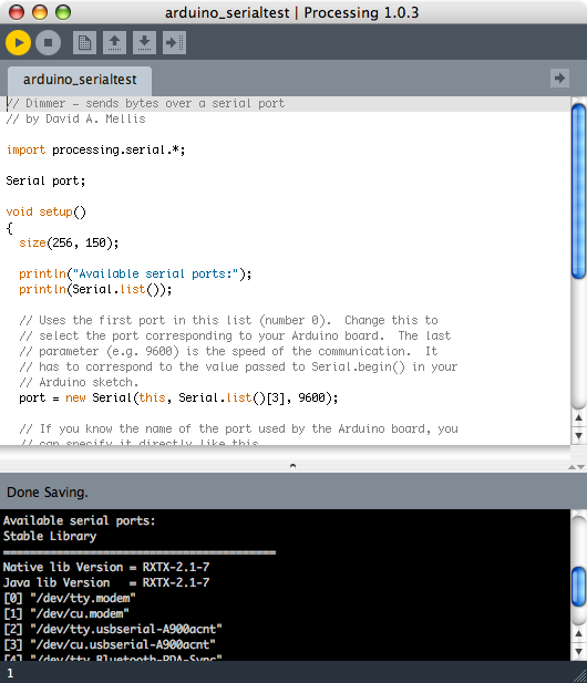
- In Processing, open a new sketch, and copy this code into it. Save this sketch as "arduino_test" or something like that. It should look like this:
- Try running this sketch. When you do, it may give you an error about "COM1" or something of that sort. You need to tell the program what serial port your arduino is connected to. When the program runs, you will see a list of Serial ports, you can see mine in the picture above. On my comnputer, I see that my serial port is the "tty.usbserial-A900acnt", which is listed as device number 2 ([2]), so I go back into the processing code and change the line that says
port = new Serial... to readport = new Serial(this, Serial.list()[2], 9600); - Now if I run the sketch again, I know that it will be properly communicating with the Arduino. You will need to modify that line to reflect whichever serial port your arduino is connected to.
- Try running this sketch. When you do, it may give you an error about "COM1" or something of that sort. You need to tell the program what serial port your arduino is connected to. When the program runs, you will see a list of Serial ports, you can see mine in the picture above. On my comnputer, I see that my serial port is the "tty.usbserial-A900acnt", which is listed as device number 2 ([2]), so I go back into the processing code and change the line that says
- Upload the original (unmodified) Dimmer code to your arduino in the arduino software. Your processor should now be running that code... waiting for input!
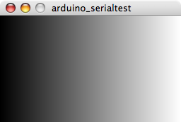
- Run your newly created arduino_test sketch in processing. You will see a small graphic window (like the one below), as you drag your mouse forwards and backwards across that window, your motor should speed up and slow down. Allright!! Now you have a simple graphical interface!
Pachube
http://www.pachube.com/ a service that enables you to connect, tag and share real time sensor data from objects, devices, buildings and environments around the world. The key aim is to facilitate interaction between remote environments, both physical and virtual."
Homework
With your sensor, build a simple computer/microprocessor project. Establish communication between the computer and processor, either controlling the device with commands from your computer program, or driving the computer program with information from the processor. You may use Processing, and adapt one of the simple examples we have seen in class, or you can use any other program you are comfortable with (Flash, MaxMSP, PD), so long as you can demonstrate it to us in class next week. We will take the first part of class to look at your ideas for these projects.
Extra
Connecting to various external devices and components: http://www.arduino.cc/playground/Main/ComponentLib

