Difference between revisions of "Students/MikeTeall"
(→Final Project) |
(→Final Project) |
||
| Line 27: | Line 27: | ||
[[Image:Mounted.jpg]] | [[Image:Mounted.jpg]] | ||
[[Image:Mounted2.jpg]] | [[Image:Mounted2.jpg]] | ||
| − | + | ||
Materials: | Materials: | ||
Revision as of 16:07, 18 March 2010
Hello
My name is Mike Teall, I am a Junior Year ICAM major through the Visual Arts department. I wanted to be an ICAM major because for whatever silly reason, I thought I would learn about Graphic Design and Programming. I have since found out that the ICAM major does not focus Graphic Arts at all and the programming is very limited. I have decided to stick it out anyways and learn that other stuff on my own and hopefully having an ICAM degree will help me as well. I am taking this class as my two quarter A/B requirement for my major. I have between a novice level and mild enthusiast level interest in electronics. I have done some soldering, wire stripping, etc. I replaced the power jack on my girlfriend's laptop, I put a new barrel connector on my power adapter for my laptop as well. I have put together several desktop systems, including my most current one which has an Intel i7 920 processor running at 3.7 Ghz with a gigantic air cooler, 6 Gigabytes of ddr3 ram running at 1600 Mhz, an ATI Radeon 5770 graphics card running crossfire x, 2 terabytes of hard disk space running in a RAID configuration, and a 750 watt power supply with a really nice case. I do not know all the ins and outs of all electronics, but I have a decent basic understanding and some limited experience to bring to the classroom with me. I am also interested in cutting edge electronics in general and feel this class would be fun for me along with giving me the most skills out of the A/B class sequences for the ICAM major in addition to providing me with some of the skills necessary to complete the ICAM senior project.
Midterm Project
"Mercury Tilt Switch"
Materials: 4 mercury tilt switches, 1 on/off toggle switch, one toilet float ball, sound chip from a birthday card, wire, solder, hot glue gun, particle board.
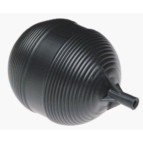
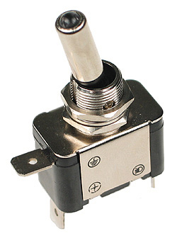
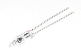
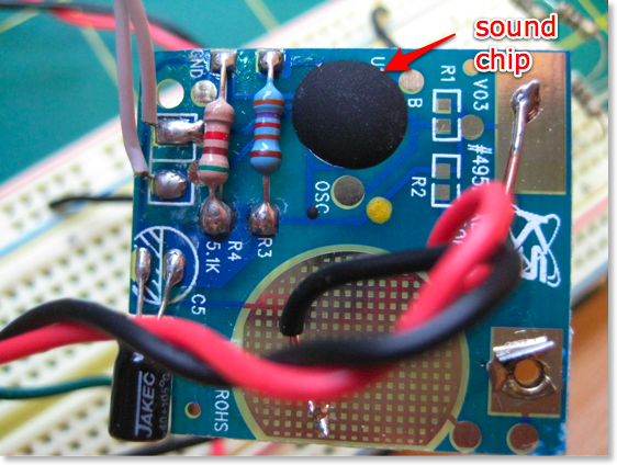
I cut the top off the float ball and removed the stem as well. I cut out a round piece of particle board and drilled a hole in the middle to fit inside. I then glued the 4 mercury switches down on the particle board. I then wired all 4 of them along with the toggle switch in series, which I connected to the sound chip. The sound will only play if the toggle switch is on, and the device is held level. All 4 mercury switches must have the ball of liquid mercury touching the two leads on the inside for the sound to play. A tilt of only a couple degrees will break the circuit.
Final Project
Materials:
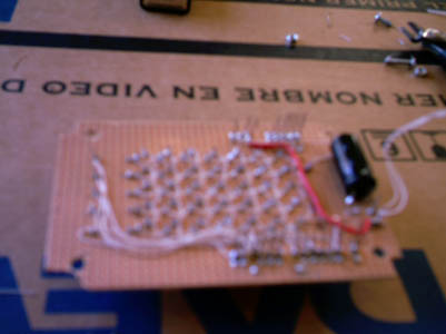
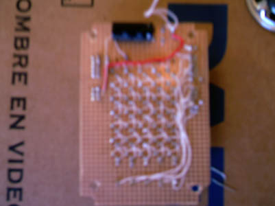
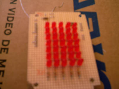
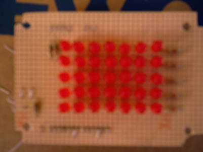
Project Box 3"x5", Freeduino, Old Analog flight joystick 15 pin, 15 pin solderable female connector, Toggle Switch, 9v Battery, 35 red LED's (only 25 used for project), a 2" 8 ohm speaker, An unprinted circuit board, screws, a whole lot of wire, and the rest of my solder.
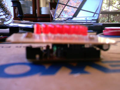
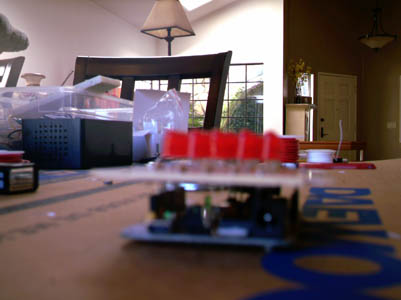
After revisions to my project due to feedback from my Instructor and Ta, I have decided to make an instrument spanning two octaves starting on c4 and ending on b5. The sound circuit will be very simple, going from digital output pin 2 of the arduino through a 100 ohm resistor, and one capacitor into the positive terminal of the speaker, and the other speaker terminal going to ground. I am going to make a 5x7 led matrix that will utilize a 5x5 portion for the project. The LED's and the sound circuit will be mounted on an unprinted circuit board. This circuit board has 19 one inch or so pieces of stiff wire soldered into it to act as pins, so the whole circuit board simply plugs directly into the top of the freeduino. There are 5 analog inputs, 11 digital outputs, 1 +5v, 2 Gnd. The control of the device is an analog joystick with x and y axis, 2 buttons, and an adjustment wheel that I am using as a third button. There will be three different modes of interaction: In Free play mode the user only has to move the joystick around on the x and y axis to produce the respective tones. In selective mode the user will move the stick to any position, but the sound will only be produced when the user presses the trigger button. For demo mode, the user simply pushes the top button and a preprogramed melody will play.
Actual Used Code:
/*
 Vis 147a Final Project
 "Analog Joystick as an instrument"
  Written by Mike Teall
- /
//initializing both indexes
 int oldindex = 0;
 int oldindex2 = 0;


 //my array of frequencies from c to b over two octaves, with one dead zone in the middle
 int myTones[] = {262, 277, 294, 311, 330, 349, 370, 392,
                 415, 440, 466, 494, 0, 523, 554, 587, 622, 659,
                 699, 740, 784, 830, 880, 932, 988};
 //this array is holding the pin numbers driving the row of my led matrix
 int myRowPins[] = {3, 4, 5, 6, 7};
 //this array is holding the pin numbers driving the Column of my led matrix
 int myColPins[] = {9, 10, 11, 12, 13};
 //this array is holding the indices to notes stored in myTones for the pre-programmed
 //tune
 int myTune[] = {14, 11, 14, 6, 15, 14, 15, 14, 11, 15, 14, 15, 6, 11, 9, 11, 9, 8, 11, 9};
 //these are note durations and used to control loop speed during pre-programmed tune
 int durations[] = {100, 100, 200, 400, 100, 100, 100, 200, 400, 100, 100, 200, 400, 100, 100, 100, 100, 100, 100, 400};
//Initialization Routine void setup() {
 // initialize serial communications (for debugging only):
 Serial.begin(9600);
 // definining these digital pins as outputs
 pinMode(3, OUTPUT);
 pinMode(4, OUTPUT);
 pinMode(5, OUTPUT);
 pinMode(6, OUTPUT);
 pinMode(7, OUTPUT);
 pinMode(9, OUTPUT);
 pinMode(10, OUTPUT);
 pinMode(11, OUTPUT);
 pinMode(12, OUTPUT);
 pinMode(13, OUTPUT);

 //Initializing Row Pins to High
 digitalWrite(3, HIGH);
 digitalWrite(4, HIGH);
 digitalWrite(5, HIGH);
 digitalWrite(6, HIGH);
 digitalWrite(7, HIGH);

 }
//Main Program Loop void loop() {
 // read the sensors:
 int val = analogRead(0);
 int val2 = analogRead(1);
 int val3 = analogRead(2);
 int val4 = analogRead(3);
 int val5 = analogRead(4);

 //map sensor inputs to useful ranges
 int selector = map(val3, 1, 850, 0, 1);
 int button1 = map(val4, 1, 850, 0, 1);
 int button2 = map(val5, 1, 850, 0, 1);

 int index = map(val, 1, 850, 0, 4);
 int index2 = map(val2, 1, 850, 0, 4);
 int index3 = index2*5;

 //continuous play mode
 if (selector == 0)
 {

   if ((index != oldindex) || (index2 != oldindex2))
   {
     //turn off old led, turn on new led
      digitalWrite(myColPins[oldindex], LOW);
      digitalWrite(myRowPins[oldindex2], HIGH);
      digitalWrite(myColPins[index], HIGH);
      digitalWrite(myRowPins[index2], LOW);
   }


     //choose a tone from the myTones array
     int thisPitch = myTones[index+index3];

     //Serial.println(button2);
     // play the pitch:
     tone(2, thisPitch, 10);

     //keep track of old index values so we can turn off the old led in case of change
     oldindex = index;
     oldindex2 = index2;
 }
     //this is trigger mode, where no sound will play unless trigger is pulled
   if (selector == 1)
   {
     if ((index != oldindex) || (index2 != oldindex2))
   {
      digitalWrite(myColPins[oldindex], LOW);
      digitalWrite(myRowPins[oldindex2], HIGH);
      digitalWrite(myColPins[index], HIGH);
      digitalWrite(myRowPins[index2], LOW);
   }


     //selects tone in case trigger is pulled
     int thisPitch = myTones[index+index3];

     //check trigger
     if (button1 == 0)
     {
       //trigger pulled, play tone
       tone(2, thisPitch, 10);
     }
     oldindex = index;
     oldindex2 = index2;
   }
   //This is the pre-programmed routine of "Final Countdown"
     //check button
   if (button2 == 0)
   {
     oldindex = 2;
     oldindex2 = 2;
     //for loop steps through the myTune array to choose indices for tones
     for (int i=0; i<20; i++)
     {
       //index for columns is i div 5
       //index for rows is i % 5
       index = myTune[i]/5;
       index2 = myTune[i]%5;
       digitalWrite(myColPins[oldindex2],LOW);
       digitalWrite(myRowPins[oldindex],HIGH);
       digitalWrite(myColPins[index2],HIGH);
       digitalWrite(myRowPins[index],LOW);

       //playing the current note of the pre programmed sequence
       tone(2, myTones[myTune[i]], (durations[i]*2));
       delay (durations[i]*2);
       oldindex = index;
       oldindex2 = index2;
       //Serial.println(index2);

     }
     //clears last light from tune sequence
     digitalWrite(myColPins[oldindex2],LOW);
     digitalWrite(myRowPins[oldindex],HIGH);
   }
}
Field Research Listed Below:
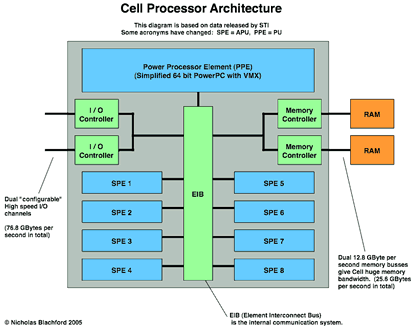
If I could link together several devices all utilizing Cell Processors in a home network as they were intended and designed for, I
would have tremendous computing power. Instead I only have one, in my Sony Playstation 3....

If I had the knowledge and the opportunity to operate and manipulate the HAARP antennas, I would carry out epic weather experiments.

Oh the fun I would have with Hubble.... I think some of the best artwork in history has come from pictures taken by the Hubble
Telescope. Given the opportunity to control Hubble, I would probably do long exposures on dark areas with no stars.

Playing with the Large Hadron Collider must be a blast.... Literally
 If I had control over all of the ATM machines and their networks, this girl wouldn't be the only one to pee herself...
