Difference between revisions of "Week 3 Lab"
(→BONUS) |
(→BONUS) |
||
| Line 57: | Line 57: | ||
Cadsoft EaglePCB - the program I have been using to make these schematics. | Cadsoft EaglePCB - the program I have been using to make these schematics. | ||
| − | If you want to get a headstart on the future, download this software: http://www.cadsoft.de/download.htm. It is free. And then you can design complete circuits, from schematic to layout to fabrication. | + | If you want to get a headstart on the future, download this software: http://www.cadsoft.de/download.htm. It is free. And then you can design complete circuits, from schematic to layout to fabrication. (It is also installed on the lab computers) |
Revision as of 23:13, 12 April 2009
from Electronic Technologies for Art
Contents
Analog Input
- File->Sketchbook->Analog->AnalogInput
The value of the input signal changes the timing of the light: the lower the signal the lower the on-off frequency, the higher the signal, the higher the frequency. We can return to this at the end of the lab.
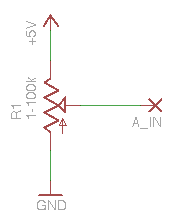
First we will use a potentiometer as our input.
Potentiometer
A_IN can be any of the Analog pins (0-5) on your Freeduino.
- Q: What will the voltage at A_IN be? What are the upper and lower values?
The important part of this sketch is the line where the microprocessor reads the analog input:
val = analogRead(potPin); // read the value from the sensor
- Q: Looking at the Arduino help for that function (
analogRead()), what do you think the valuevalwill be for those highest and lowest voltages at your A_IN pin? - Q: How can you verify your guess? Try and verify your values, in some plausible manner. Anything goes!!
other loads
photoresistor
- taking the photoresistor from your 147A kit, it has a resistance of ~160k - ~10k (depending on your lighting conditions)
- Q: With the same R2 resistor (10k) from above, replacing R1 with the photoresistor, what range of voltages (and corresponding data values) would you expect to see at your A_IN pin?
- Q: Using methods you invented above, verify your data readings.
strain gauge
flex sensor
Analog Output
Continually varying signals, rather than discrete "steps". Your processor approximates Analog signals with PWM.
LED Dimming
- File->Sketchbook->Examples->Analog->Fading
analogWrite(ledpin, value); // sets the value (range from 0 to 255)
PWM (pulse width modulation)
- lights, fading
<youtube v="62gWVWCyw_w" loop="true"/>
ultrasonic rangefinder
Motor Speed Control
- Basic motor control (DC motors) see week 5
Sound, Tone Generation
- sounds, tone generation
- frequency, not duty cycle.
BONUS
Cadsoft EaglePCB - the program I have been using to make these schematics.
If you want to get a headstart on the future, download this software: http://www.cadsoft.de/download.htm. It is free. And then you can design complete circuits, from schematic to layout to fabrication. (It is also installed on the lab computers)

