Students/SharonPtashek
Sharon Ptashek. 2nd Year VisArts Media with Computing Emphasis.
I am a computer artist who is interested in using digital technologies to create works of art and new media. I create projects that require knowledge and creativity using java, c programming, illustrator, photoshop, flash, dreamweaver, and painting. The way you can combine artistic ideas into new media is something that I strive to improve on. I have a lot of work experience in terms of graphic design, marketing, and animation. I want to pursue a master degree in business electronics which is why I am so determined on earning amy first degree in Media with Computing Emphasis.
I have been set on working on computer art since I was 15 years of age, but I always had an interest in electronics and the way they work. Ever since I realized that I was serious about computers and new media (as my future career) I have maintained some kind of an internship or a job in the field.
____________________________________________________________________________
FINAL PROJECT
Signaling Fire Truck
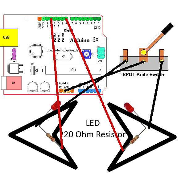
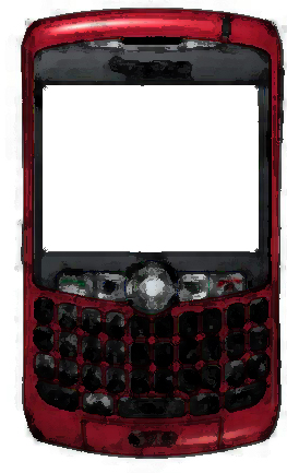
The project creates two blinking signaling arrows that are located on a Lego made toy truck. The blinkers signal if the driver wants to go to the left or the right. Each of these blinkers, or arrows, contains 1 LED and one 220 ohm resister inside. The code, which was imported into the Arduino, allows for both of the left and right arrows to continually blink. Inside the left arrow the 220 ohm resistor is soldered to the LED’s positive side on one of its sides, and on the other side it is soldered to a wire that is connected to the Arduino’s digital pin 12. The negative side of the LED is then connected to left side of the SPDT knife switch terminals. Inside the right arrow the 220 ohm resistor is soldered to the LED’s positive side on one of its sides, and on the other side it is soldered to a wire that is connected to the Arduino’s digital pin 8. The negative side of the LED is then connected to right side of the SPDT knife switch terminals. The middle part of the SPDT switch terminals is the connected to the ground (Gnd) power of the Arduino board.
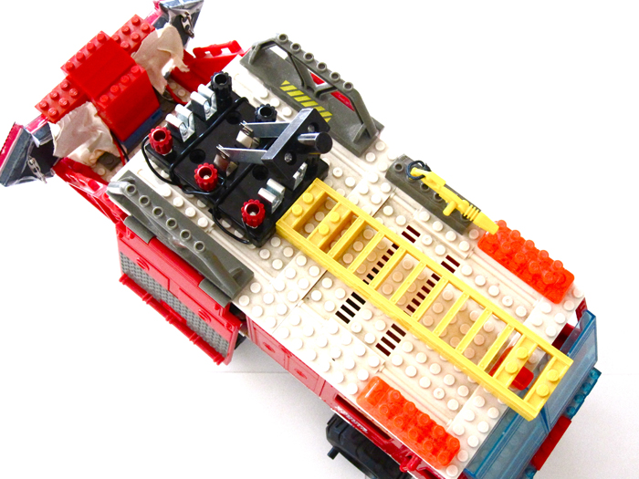
I constructed a Lego board fire truck out of Lego pieces and parts and the attached two signaling arrows to the back of the truck. In order to create these blinking arrows, I bought two close arrow toys and inserted inside the LED and resistor, and then drilled a whole in each of the arrows that would allow the wires to exit and connect to the Arduino bored itself. These arrows will allow the truck to signal to which direction it is going. The signaling arrows will blink based on a realistic timing status with the help of the Arduino board. Thus, this project creates an interactive and constructive object that has technological means as part of it’s game or usage.
DIAGRAM
CODE
     // Sharon Ptashek
     // This Arduino program allows for two LED’s to blink together at the same time

     // declares variables
     int ledPin = 12;                // LED is connected to digital pin 12
     int LPin = 8;                  // LED is connected to digital pin 8


     void setup()                    // run once

     {

       pinMode(ledPin, OUTPUT);      // sets the digital pin as output
       pinMode(LPin, OUTPUT);        // sets the digital pin as output

     }


     void loop()                     // run over and over again

     {

       blink(2000);  //code that makes the LED blink

     }


     //turns the LED on

     void on(){

       digitalWrite(ledPin,HIGH); //sets the pin HIGH and thus turn LED on
       digitalWrite(LPin,HIGH);  //sets the pin HIGH and thus turn LED on
     }


     //turns the LED off

     void off(){

       digitalWrite(ledPin,LOW); //sets the pin LOW and thus turn LED off
       digitalWrite(LPin,LOW);  //sets the pin LOW and thus turn LED off
     }


     //makes the LED blink

     void blink(int time){

       on();                                             // sets the LED on

       delay(time/6); // sets the delay time according to the humeral value

       off();                                            // sets the LED off

       delay(time/6); // sets the delay time according to the humeral value

     }
PRODUCT
____________________________________________________________________________
MIDTERM PROJECT
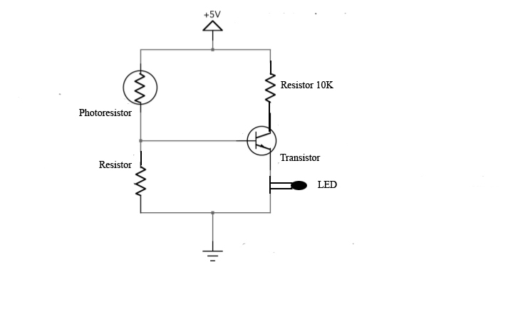
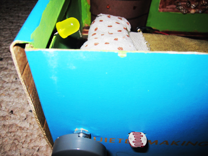
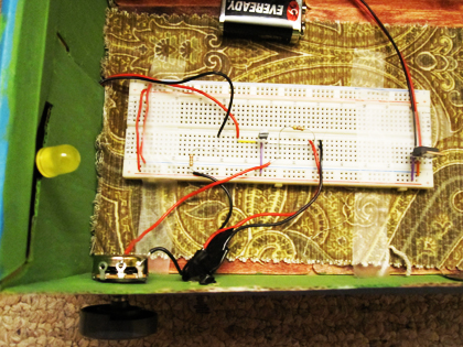
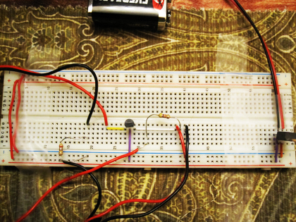
For my midterm project I have created an automatic light bulb switch. I used a photoresistor that senses when there is light and thus the light in the bedroom turns off and as soon as it's dark the light bulb turns on. The idea for having an automatic light switch is that an individual will never have to forget to turn it on or off as it works automatically. I used a photoresistor, a variable resistor (the 10k), a few resistors, an LED, a breadboard, DC battery as a power supplier, wires, a regulator that will fix the light level as desired by the user, and an iron solder to connect the wires with the flux cores. The transistor controls the switch that will allow the light to turn on using battery power. A transistor is an electronic component that could be used as an electronically operated switch through its three contacts: the emitter (E), base (B) and collector (C). The transistor opens the collector/emitter when a small current is present at the transistor’s base. The “automatic night light” is placed within a Tuscany like bedroom where the LED turns on every time the door closes and turns off every time the door opens. I have created a 3-D model of the Tuscan room and placed the light within the interior of the model. Increasing the brightness changes the resistance of the photoresistor, because as it gets brighter there will be less resistance. When the photoresistor has less resistance the transistor’s base has a greater voltage. In order to fine-tune the circuit, I used a regulator knob that will sense the light and dark conditions. After fine-tuning the circuit, the LED lights up whenever the light hits the photoresistor. The wires are all placed through “the wall” of the bedroom and the breadboard is placed under the bed, or “the ground”, with the intensions of making the model more aesthetically pleasing.
Diagrams:
Images:
 _______________________________________________________________________________________________________________________
____________________________________________________________________________________________________
Final Proposal
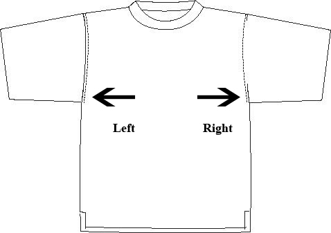
To create a signaling shirt that could be used by bikers at night. There will be a right and left arrows on the back of the shirt and the biker will press a button in order to inform whether they are going right or left. The arduino board will be used in order to make the button stimulate a blinking reaction that will allow others to tell whether the biker is going right or left. This project will use an arduino with some processing on it, wires, some type of buttons/switch, and LED's.
____________________________________________________________________________________________________
Midterm Project Proposal
My proposal for the Midterm Project is to create a “regulated emergency light switch”. I will be using a photoresistor, a variable resistor (most likely the 100k), a few resistors, a light bulb or/LED, power supply, breadboard, DC battery, AC adaptor, power relay, and wires. The transistor is a semiconductor device that will act as electrically controlled switch (Pg 439). The variable resistor will allow the user to set the exact amount of light wanted for the light to turn on, which will be detected by the photoresistor. The transistor will control the switch that will allow the light to turn on using battery power. The resistors are going to be powered by the AC adapter.
The “regulated emergency light switch” will be placed into a Tuscany like bedroom that will turn on every time the door closes and turns off every time the door opens. I will create a 3-D model of the Tuscan room and place the light within the interior of the model.
______________________________________________________________
