Week 3 Lab
From Robert-Depot
from Electronic Technologies for Art
Contents
Analog Input
- File->Sketchbook->Analog->AnalogInput
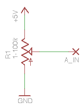
Potentiometer
- A_IN can be any of the Analog pins (0-5) on your Freeduino.
- Q: What will the voltage at A_IN be? What are the upper and lower values?
- The important part of this sketch is the line where the microprocessor reads the analog input:
val = analogRead(potPin); // read the value from the sensor
- Q: Looking at the Arduino help for that function (
analogRead()), what do you think the valuevalwill be for those highest and lowest voltages at your A_IN pin? - Q: How can you verify your guess? Try and verify your values, in some way. Anything goes!!!
other loads
photoresistor
- taking the photoresistor from your 147A kit, it has a resistance of ~160k - ~10k (depending on your lighting conditions)
- Q: With the same 10k resistor and setup from the schematic above, replacing the pot with the photoresistor, what range of voltages (and corresponding data values) would you expect to see at your A_IN pin?
strain gauge
ultrasonic rangefinder
Analog Output
LED Dimming
- File->Sketchbook->Examples->Analog->Fading
analogWrite(ledpin, value); // sets the value (range from 0 to 255)
PWM (pulse width modulation)
- lights, fading
<youtube v="62gWVWCyw_w" loop="true"/>
Motor Speed Control
- Basic motor control (DC motors) see week 5
Sound, Tone Generation
- sounds, tone generation
